
What is inside an E-HUB energy storage container?
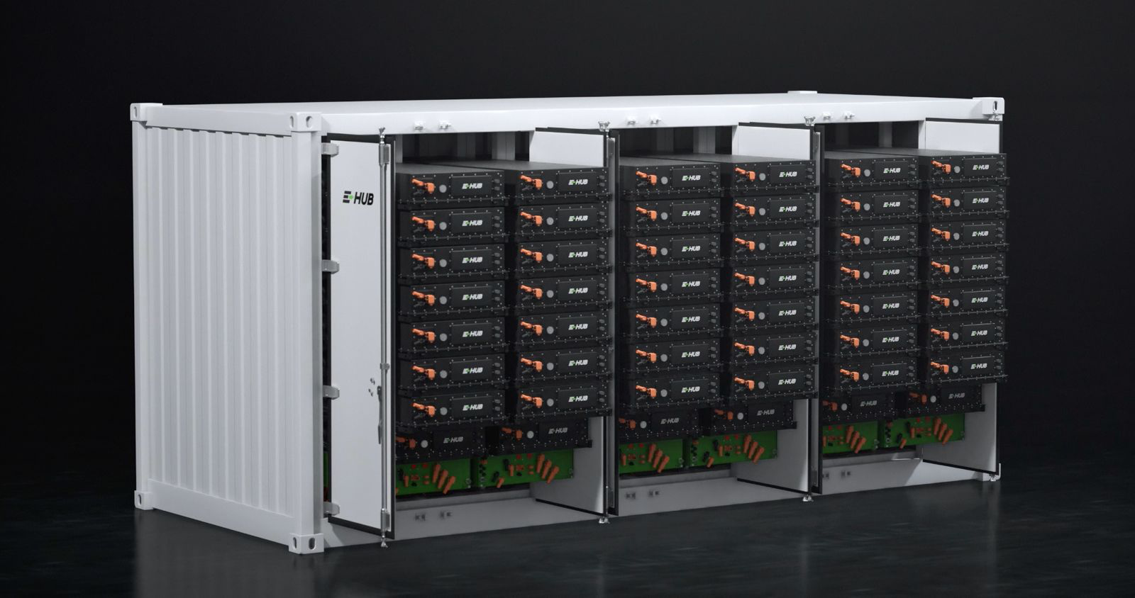
A containerised battery energy storage system may look simple from the outside, but inside it is a coordinated system of battery packs, monitoring electronics, cooling equipment, protection devices and communication interfaces. In the E-HUB solution, these layers work together to support battery operation, diagnostics and integration with the wider site.
LFP cells in cell-to-pack battery packs
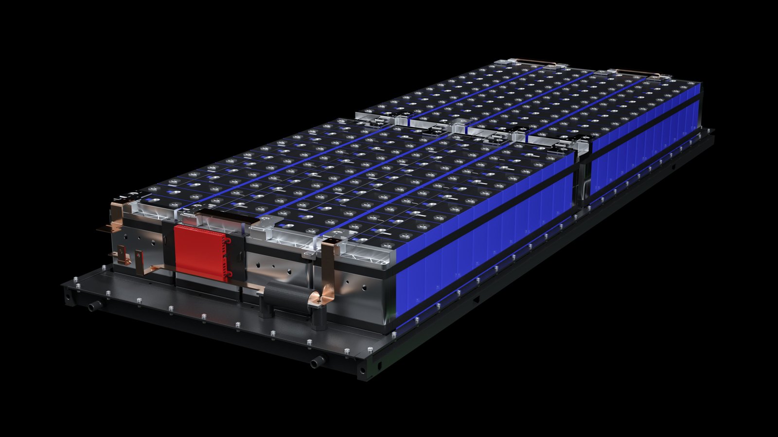
The battery section uses LFP (lithium iron phosphate) cells integrated directly into battery packs using cell-to-pack, or CTP, architecture. LFP describes the cell chemistry, while CTP describes the way cells are integrated into the pack.
The source material highlights three reasons for using LFP: safety, long service life and stability in intensive cyclic operation. It states that the best LFP cells can reach approximately 6,000 to 12,000 charge and discharge cycles before noticeable capacity degradation appears. Each pack combines the cells, electrical connections, a cooling plate and BMS measurement components. Multiple packs are then combined into battery clusters.
A three-level Battery Management System
The Battery Management System (BMS) operates across three levels, with a different responsibility at each level.
Level 1 – Pack. The BMS measures individual cell voltages and temperatures and performs cell balancing.
Level 2 – Cluster. At cluster level, the system measures current, monitors insulation and determines state of charge.
Level 3 – Battery system. At the highest level, the BMS collects alarms and exchanges information with the Energy Management System (EMS) and the Power Conversion System (PCS).
This hierarchy allows battery data to be collected close to the cells and then consolidated for system-level supervision and control.
Liquid cooling inside the container
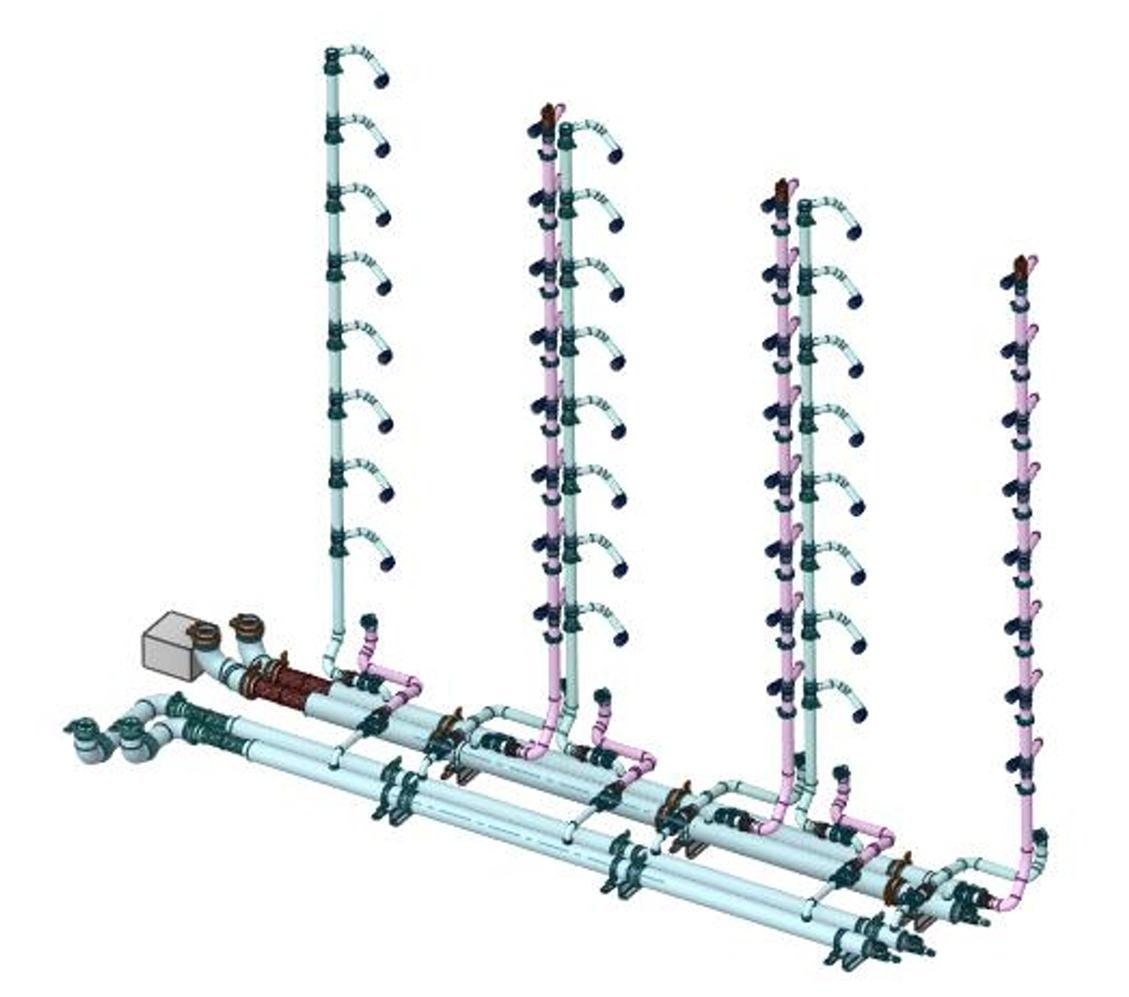
Battery performance and lifetime depend strongly on thermal conditions, so cooling is an integral part of the container design. Coolant lines deliver fluid to the cooling plates of the battery packs. A cooling unit and pumps maintain circulation, while the control logic responds to measured temperatures.
The PCS uses a separate cooling circuit. According to the source material, this separation prevents thermal loads from the power electronics from being transferred directly to the battery section.
Protection on several levels
Operational safety is built around a multilayer protection concept. Temperature, smoke and gas sensors provide signals to the protection system. Electrical protection includes devices such as fuses, contactors and insulation monitoring.
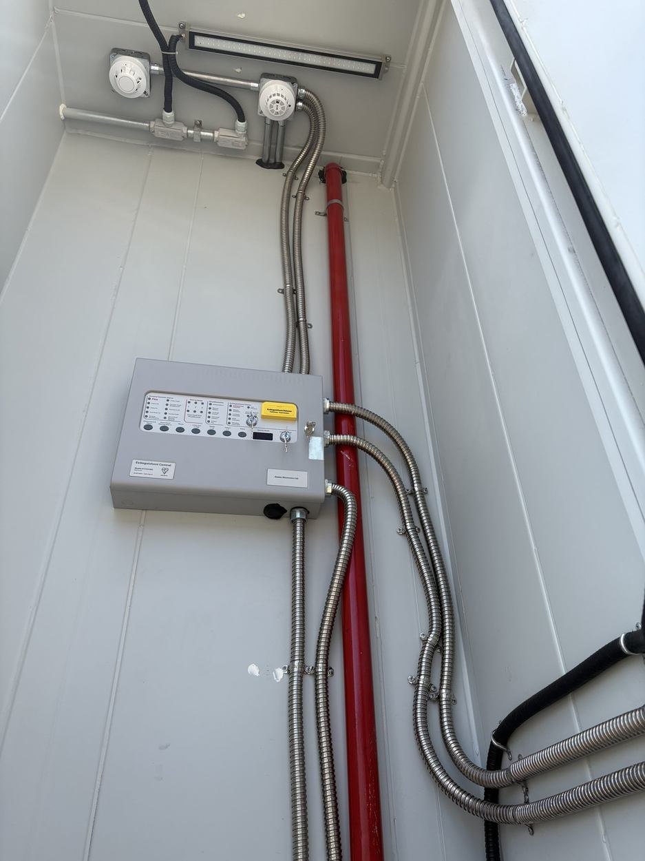
The fire-protection system includes a control unit, signalling and extinguishing equipment. The exact response to an event depends on the system protection logic, while the final equipment configuration is selected for the specific container configuration.
Communication with the site
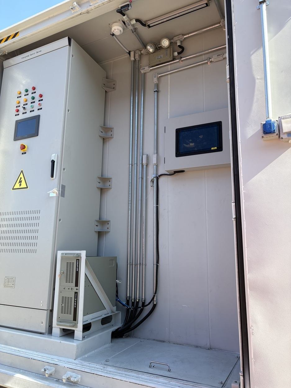
Inside the storage system, CAN and RS-485 are used for data exchange between devices. Modbus TCP over Ethernet provides communication with the higher-level site control system.
The communication interface, the data set to be exchanged and the connection configuration are agreed for each project. This is important because a battery storage system does not operate in isolation: it needs to exchange information with the other systems responsible for site operation and energy management.
Access, diagnostics and modular service
The container layout is designed to support diagnostics and modular servicing. The source document states that individual battery packs or PCS modules can be replaced without dismantling the supporting racks or the container structure.
Full logging of events and operating readings also supports predictive maintenance. Instead of relying only on reactive service after a fault, operators can use recorded system data to identify trends and investigate abnormal behaviour earlier.
One container, several coordinated subsystems
An E-HUB container therefore combines much more than battery cells. The complete architecture brings together LFP battery packs, a multi-level BMS, liquid cooling, electrical and fire protection, communication interfaces and service access.
The result is a system in which battery operation, thermal management, protection and data exchange are designed as parts of one coordinated platform rather than as isolated components.
Let us discuss the right storage configuration for your project.
office@e-hub-bess.com